
Main -> Tech -> Electrical Engineering -> 44780 LCD

Main -> Tech -> Electrical Engineering -> 44780 LCD |
| 44780 LCD | UMPS | Web Pages |
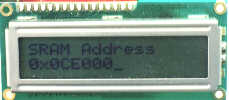
LCDs can add a lot to your application in terms of providing an useful interface for the user, debugging an application or just giving it a "professional" look. The most common type of LCD controller is the Hitatchi 44780 which provides a relatively simple interface between a processor and an LCD. Using this interface is often not attempted by inexperienced designers and programmers because it is difficult to find good documentation on the interface, initializing the interface can be a problem and the displays themselves are expensive.
Click
here
to download Hitachi's |
I have worked with Hitatchi 44780 based LCDs for a while now and I have to say that I don't believe any of these perceptions. LCDs can be added quite easily to an application and use as few as three digital output pins for control. As for cost, LCDs can be often pulled out of old devices or found in surplus stores for less than a dollar.
The purpose of this page is to give a brief tutorial on how to interface with Hitatchi 44780 based LCDs. I have tried to provide the all the data necessary for successfully adding LCDs to your application.
The most common connector used for the 44780 based LCDs is 14 pins in a row, with pin centers 0.100" apart. The pins are wired as:
| Pins | Description |
|---|---|
| 1 | Ground |
| 2 | Vcc |
| 3 | Contrast Voltage |
| 4 | "R/S" _Instruction/Register Select |
| 5 | "R/W" _Read/Write LCD Registers |
| 6 | "E" Clock |
| 7 - 14 | Data I/O Pins |
As you would probably guess from this description, the interface is a parallel bus, allowing simple and fast reading/writing of data to and from the LCD.
This waveform will write an ASCII Byte out to the LCD's screen.
The ASCII code to be displayed is eight bits long and is sent to the LCD either
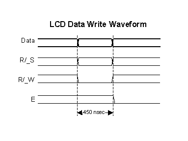 four or eight bits at a time. If four bit mode is used, two "nybbles" of data
(Sent high four bits and then low four bits with an "E" Clock pulse with each
nybble) are sent to make up a full eight bit transfer. The "E" Clock is used to
initiate the data transfer within the LCD.
Sending parallel data as either four or eight bits are the two primary modes of operation. While there are secondary considerations and modes, deciding how to send the data to the LCD is most critical decision to be made for an LCD interface application.
Eight bit mode is best used when speed is required in an application and at least ten I/O pins are available. Four bit mode requires a minimum of six bits. To wire a microcontroller to an LCD in four bit mode, just the top four bits (DB4-7) are written to.
The "R/S" bit is used to select whether data or an instruction is being transferred between the microcontroller and the LCD. If the Bit is set, then the byte at the current LCD "Cursor" Position can be read or written. When the Bit is reset, either an instruction is being sent to the LCD or the execution status of the last instruction is read back (whether or not it has completed).
The different instructions available for use with the 44780 are shown in the table below:
| R/S | R/W | D7 | D6 | D5 | D4 | D3 | D2 | D1 | D0 | Instruction/Description |
|---|---|---|---|---|---|---|---|---|---|---|
| 4 | 5 | 14 | 13 | 12 | 11 | 10 | 9 | 8 | 7 | Pins |
| 0 | 0 | 0 | 0 | 0 | 0 | 0 | 0 | 0 | 1 | Clear Display |
| 0 | 0 | 0 | 0 | 0 | 0 | 0 | 0 | 1 | * | Return Cursor and LCD to Home Position |
| 0 | 0 | 0 | 0 | 0 | 0 | 0 | 1 | ID | S | Set Cursor Move Direction |
| 0 | 0 | 0 | 0 | 0 | 0 | 1 | D | C | B | Enable Display/Cursor |
| 0 | 0 | 0 | 0 | 0 | 1 | SC | RL | * | * | Move Cursor/Shift Display |
| 0 | 0 | 0 | 0 | 1 | DL | N | F | * | * | Set Interface Length |
| 0 | 0 | 0 | 1 | A | A | A | A | A | A | Move Cursor into CGRAM |
| 0 | 0 | 1 | A | A | A | A | A | A | A | Move Cursor to Display |
| 0 | 1 | BF | * | * | * | * | * | * | * | Poll the "Busy Flag" |
| 1 | 0 | D | D | D | D | D | D | D | D | Write a Character to the Display at the Current Cursor Position |
| 1 | 1 | D | D | D | D | D | D | D | D | Read the Character on the Display at the Current Cursor Position |
The bit descriptions for the different commands are:
"*" - Not Used/Ignored.  This bit can be either "1" or "0"

Set Cursor Move Direction:
  ID - Increment the Cursor After Each Byte Written to Display if Set
   S - Shift Display when Byte Written to Display

Enable Display/Cursor
   D - Turn Display On(1)/Off(0)
   C - Turn Cursor On(1)/Off(0)
   B - Cursor Blink On(1)/Off(0)

Move Cursor/Shift Display
  SC - Display Shift On(1)/Off(0)
  RL - Direction of Shift Right(1)/Left(0)

Set Interface Length
  DL - Set Data Interface Length 8(1)/4(0)
   N - Number of Display Lines 1(0)/2(1)
   F - Character Font 5x10(1)/5x7(0)

Poll the "Busy Flag"
  BF - This bit is set while the LCD is processing

Move Cursor to CGRAM/Display
   A - Address

Read/Write ASCII to the Display
   D - Data
Reading Data back is best used in applications which required data to be moved back and forth on the LCD (such as in applications which scroll data between lines). The "Busy Flag" can be polled to determine when the last instruction that has been sent has completed processing. In most applications, I just tie the "R/W" line to ground because I don't read anything back. This simplifies the application because when data is read back, the microcontroller I/O pins have to be alternated between input and output modes.
For most applications, there really is no reason to read from the LCD. I usually tie "R/W" to ground and just wait the maximum amount of time for each instruction (4.1 msecs for clearing the display or moving the cursor/display to the "home position", 160 usecs for all other commands). As well as making my application software simpler, it also frees up a microcontroller pin for other uses. Different LCDs execute instructions at different rates and to avoid problems later on (such as if the LCD is changed to a slower unit), I recommend just using the maximum delays given above.
In terms of options, I have never seen a 5x10 LCD display. This means that the "F" bit in the "Set Interface Instruction" should always be reset (equal to "0").
Before you can send commands or data to the LCD module, the Module must be initialized. For eight bit mode, this is done using the following series of operations:
In describing how the LCD should be initialized in four bit mode, I will specify writing to the LCD in terms of nybbles. This is because initially, just single nybbles are sent (and not two, which make up a byte and a full instruction). As I mentioned above, when a byte is sent, the high nybble is sent before the low nybble and the "E" pin is toggled each time four bits is sent to the LCD. To initialize in four bit mode:
All following instruction/Data Writes require two nybble writes.
Once the initialization is complete, the LCD can be written to with data or instructions as required. Each character to display is written like the control bytes, except that the "R/S" line is set. During initializiation, by setting the "S/C" bit during the "Move Cursor/Shift Display" command, after each character is sent to the LCD, the cursor built into the LCD will increment to the next position (either right or left). Normally, the "S/C" bit is set (equal to "1") along with the "R/L" bit in the "Move Cursor/Shift Display" command for characters to be written from left to right (as with a "Teletype" video display).
One area of confusion is how to move to different locations on the display and, as a follow on, how to move to different lines on an LCD display. The following table shows how different LCD displays that use a single 44780 can be set up with the addresses for specific character locations. The LCDs listed are the most popular arrangements available and the "Layout" is given as number of columns by number of lines:
| LCD Layout | Top Left Character | Ninth Character | Second Line | Third Line | Fourth Line | Comments |
|---|---|---|---|---|---|---|
| 8x1 | 0 | N/A | N/A | N/A | N/A | Single 44780/No Support Chip |
| 16x1 | 0 | 0x040 | N/A | N/A | N/A | Single 44780/No Support Chip |
| 16x1 | 0 | 8 | N/A | N/A | N/A | 44780 with Support Chip. This is quite rare |
| 8x2 | 0 | N/A | 0x040 | N/A | N/A | Single 44780/No Support Chip |
| 10x2 | 0 | 8 | 0x040 | N/A | N/A | 44780 with Support Chip |
| 16x2 | 0 | 8 | 0x040 | N/A | N/A | 44780 with Support Chip |
| 20x2 | 0 | 8 | 0x040 | N/A | N/A | 44780 with Support Chip |
| 24x2 | 0 | 8 | 0x040 | N/A | N/A | 44780 with Support Chip |
| 30x2 | 0 | 8 | 0x040 | N/A | N/A | 44780 with Support Chip |
| 32x2 | 0 | 8 | 0x040 | N/A | N/A | 44780 with Support Chip |
| 40x2 | 0 | 8 | 0x040 | N/A | N/A | 44780 with Support Chip |
| 16x4 | 0 | 8 | 0x040 | 0x020 | 0x060 | 44780 with Support Chip |
| 20x4 | 0 | 8 | 0x040 | 0x020 | 0x060 | 44780 with Support Chip |
| 40x4 | U/N | U/N | U/N | U/N | U/N | Two 44780 with Support Chips. Addressing is device specific |
The "Ninth Character" is the position of the Ninth character on the first line.
Most LCD displays have a 44780 and support chip to control the operation of the LCD. The 44780 is responsible for the external interface and provides sufficient control lines for sixteen characters on the LCD. The support chip enhances the I/O of the 44780 to support up to 128 characters on an LCD. From the table above, it should be noted that the first two entries ("8x1", "16x1") only have the 44780 and not the support chip. This is why the ninth character in the 16x1 does not "appear" at address 8 and shows up at the address that is common for a two line LCD.
I've included the 40 character by 4 line ("40x4") LCD because it is quite common. Normally, the LCD is wired as two 40x2 displays. The actual connector is normally sixteen bits wide with all the fourteen connections of the 44780 in common, except for the "E" (Strobe) pins. The "E" strobes are used to address between the areas of the display used by the two devices. The actual pinouts and character addresses for this type of display can vary between manufacturers and display part numbers.
Note that when using any kind of multiple 44780 LCD display, you should probably only display one 44780's Cursor at a time.
Cursors for the 44780 can be turned on as a simple underscore at any time using the "Enable Display/Cursor" LCD instruction and setting the "C" bit. I don't recommend using the "B" ("Block Mode") bit as this causes a flashing full character square to be displayed and it really isn't that attractive.

The LCD can be thought of as a "Teletype" display because in normal operation, after a character has been sent to the LCD, the internal "Cursor" is moved one character to the right. The "Clear Display" and "Return Cursor and LCD to Home Position" instructions are used to reset the Cursor's position to the top right character on the display.
To move the Cursor, the "Move Cursor to Display" instruction is used. For this instruction, bit 7 of the instruction byte is set with the remaining seven bits used as the address of the character on the LCD the cursor is to move to. These seven bits provide 128 addresses, which matches the maximum number of LCD character addresses available. The table above should be used to determine the address of a character offset on a particular line of an LCD display.
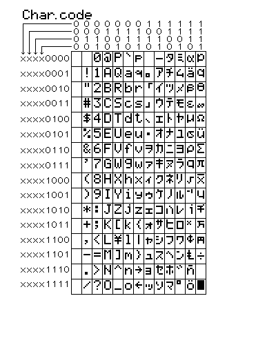
The Character Set available in the 44780 is basically ASCII. I say "basically" because some characters do not follow the ASCII convention fully (probably the most significant difference is 0x05B or "\" is not available). The ASCII Control Characters (0x008 to 0x01F) do not respond as control characters and may display funny (Japanese) characters. The LCD Character Set shown below is courtesy of Peer Ouwehand and his excellent LCD page:
Eight programmable characters are available and use codes 0x000
to 0x007. They are programmed by pointing the LCD's "Cursor" to the Character
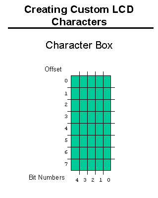 Generator RAM ("CGRAM") Area at eight times the character address. The next
eight characters written to the RAM are each line of the programmable character,
starting at the top.
I like to represent this as eight squares by five as is shown in the diagram to the right. Above, I noted that most displays were 7 pixels by 5 for each character, so the extra row may be confusing. Each LCD character is actually eight pixels high, with the bottom row normally used for the underscore cursor. The bottom row can be used for graphic characters, although if you are going to use a visible underscore cursor and have it at the character, I recommend that you don't use it (ie set the line to 0x000).
Using this box, you can draw in the pixels that define your special character and then use the bits to determine what the actual data codes are. When I do this, I normally use a piece of graph paper and then write hex codes for each line, as I show in the lower right diagram. This diagram shows the first character used in the "Walking Man" "Animate" examples that can be found below.
For the "Animate" applications, I use "character" rotation for the animations. This means that instead of changing the character each time the man moves, I simply display a different character. Doing this means that only two bytes (moving the cursor to the character and the new character to display) have to be sent to the LCD. If animation was accomplished by redefining the characters, then ten characters would have to be sent to the LCD (one to move into the CGRAM space, the eight defining characters and an instruction returning to display RAM). If multiple characters are going to be used or more than eight pictures for the animation, then you will have to rewrite the character each time.
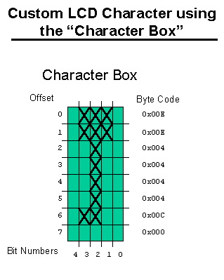
The user defined character line information is saved in the LCD's "CGRAM" area. This sixty four bytes of memory is accessed using the "Move Cursor into CGRAM" instruction in a similar manner to that of moving the cursor to a specific address in the memory with one important difference.
This difference is that each character starts at eigth times it's character value. This means that user definable character 0 has it's data starting at address 0 of the CGRAM, character 1 starts at address 8, character 2 starts at address 0x010 (16) and so on. To get a specific line within the user definable character, its offset from the top (the top line has an offset of 0) is added to the starting address. In most applications, characters are written to all at one time with character 0 first. In this case, the instruction 0x040 is written to the LCD followed by all the user-defined characters.
A special note for Wirz Electronics "SLI-OEM" users. When the
new characters are defined, it is a good idea to make sure that the upper three
bits are set in the user defined character byte. When the "Move Cursor into CGRAM"
instruction is received, the SLI-OEM goes into a special mode where the character
row counter is not updated when a new character is received. This mode is turned
off when a new instruction is sent to the SLI-OEM or an ASCII "Backspace",
"Carriage Return", "Line Feed" or "Form Feed" character is received. Since all
these characters are valid LCD user defined character line definitions, you will
find that the SLI-OEM is not interpreting the data correctly. If I was making the
"Man" symbol above for displaying on the SLI-OEM, I would use the byte 0x0EE for the
first line instead of 0x00E.
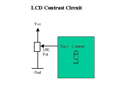
The last aspect of the LCD to discuss is how to specify a contrast voltage to the Display. I typically use a potentiometer wired as a voltage divider. This will provide an easily variable voltage between Ground and Vcc, which will be used to specify the contrast (or "darkness") of the characters on the LCD screen. You may find that different LCDs work differently with lower voltages providing darker characters in some and higher voltages do the same thing in others.
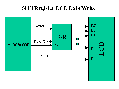
There are a variety of different ways of wiring up an LCD. Above,
I noted that the 44780 can interface with four or eight bits. To simplify the
demands in microcontrollers, a shift register is often used (as is shown in the
diagram below) to reduce the number of I/O pins to three.
This can be further reduced by using the circuit shown below in which the serial data is combined with the contents of the shift register to produce the "E" strobe at the appropriate interval.
This circuit "ANDs" (using the 1K resistor and IN914 diode) the output of the sixth "D-Flip Flop" of the 74LS174 and the "Data" bit from the device writing to the LCD to form the "E" Strobe. This method requires one less pin than the three wire interface and a few more instructions of code.
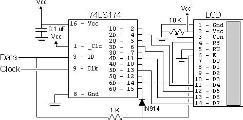
I normally use a 74LS174 wired as a shift register (as is shown in the schematic diagram) instead of a serial-in/parallel-out shift register. This circuit should work without any problems with a dedicated serial-in/parallel-out shift register chip, but the timings/clock polarities may be different. When the 74LS174 is used, note that the data is latched on the rising (from logic "low" to "high") edge of the clock signal.
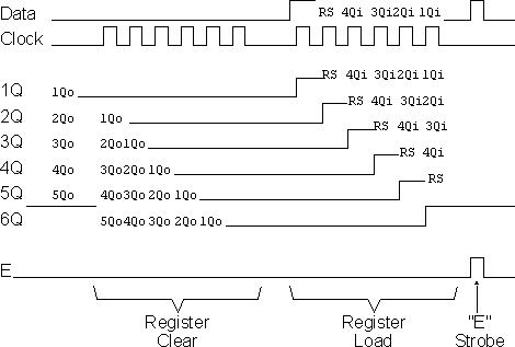
In the diagram to the right, I have shown how the shift register is written to for this circuit to work. Before data can be written to it, the shift register is cleared by loading every latch with zeros. Next, a "1" (to provide the "E" Gate) is written followed by the "R/S" bit and the four data bits. Once the is loaded in correctly, the "Data" line is pulsed to Strobe the "E" bit. The biggest difference between the three wire and two wire interface is that the shift register has to be cleared before it can be loaded and the two wire operation requires more than twice the number of clock cycles to load four bits into the LCD.
I've used this circuit with the PICMicro, 8051 and AVR and it really makes the wiring of an LCD to a microcontroller very simple. A significant advantage of using a shift register, like the two circuits shown here, data to the LCD is the lack of timing sensitivity that will be encountered. The biggest issue to watch for is to make sure the "E" Strobe's timing is within specification (ie greater than 450 nsecs), the shift register loads can be interrupted without affecting the actual write. This circuit will not work with Open-Drain only outputs (something that catches up many people).
One note about the LCD's "E" Strobe is that in some documentation it is specified as "high" level active while in others, it is specified as falling edge active. It seems to be falling edge active, which is why the 2-wire LCD interface presented below works even if the line ends up being high at the end of data being shifted in. If the falling edge is used (like in the 2-wire interface) then make sure that before the "E" line is output on "0", there is at least a 450 nsecs delay with no lines changing state.
The following "C" psuedo-code can be used for writing a nybble to the two wire circuit:
LCDNybble(char Nybble, char RS)
{

int i;


  Data = 0;                      //  Clear the '174
  for (i = 0; i < 6; i++) {      //  Repeat for six bits
    Clock = 1; Clock = 0;        //  Write the "0"s into the '174
  }

  Data = 1;                      //  Output the "AND" Value
  Clock = 1; Clock = 0;

  Data = RS;                     //  Output the RS Bit Value
  Clock = 1; Clock = 0;

  for (i = 0; i < 4; i++) {      // Output the Nybble
    if ((Nybble & 0x008) != 0)
      Data = 1;                  // Output the High Order Bit
    else
      Data = 0;
    Clock = 1; Clock = 0;        //  Strobe the Clock
    Nybble = Nybble << 1;        // Shift up Nybble for Next Byte
  }

  Clock = 1; Clock = 0;          // Toggle the "E" Clock Bit

} // End LCDNybble
The table below gives a list of LCD sample code for different microcontrollers and operations discussed on this page. Over time, I will work at filling it out with the sample assembly code for the different devices. The microcontroller circuits are very simple with just a crystal and reset resistor or capacitor. Note the device and speed that it is running at along with the Assembler that I used.
| Device | 8 Bit LCD Interface | 4 Bit LCD Interface | 3 Wire LCD Interface | 2 Wire LCD Interface | Animation | Comments |
|---|---|---|---|---|---|---|
| PICMicro | 2wirepic.asm | 4 MHz 16C84 for MPASM |